|
|
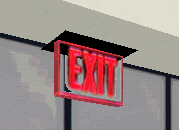
Developer's Tip - Reading RWX FilesGreetings everyone! Stacee here. It's been a very busy few months here at headquarters and because of that there wasn't an article last month. But we were determined to get one out this time around, and Oleyo needed a break, so here I am! I'm not as good at this stuff as him, but I'll give it a go. :) I had thought maybe some tips and hints from the art department and from fellow builders in AW would be an excellent grab bag of stuff to put here, but Moff, um,...oops, sorry, I mean Baro brought up a very good subject that I decided might be better to consider. Have to save the goodies for another time I'm afraid! This time around we'll be taking a look at reading .rwx files in Notepad. Why? Knowing how to read these files can go a long way in helping you maximize your work and it allows you to do things to objects that you otherwise might not be able to do. Active Worlds' first objects were built using Notepad; at the time, that's all there was. Today we use programs like Truespace or 3D Studio Max, which have made model-making much easier. Nonetheless, I can't count all the times I still go back into the .rwx file to make changes. "But have you ever looked at one of those things?!" you say,"They're so..so.....complex!" Not once you learn the lingo. *smiles* So are you ready? Here we go! Taking a Look at .RWX files First, lets get an example up here of an .rwx file and look at it piece by piece. We'll take the .rwx of the exit sign pictured below. It's made up of one panel and one cube.
##### COBDump3: V3.00.346 by HamFon@ActiveWorlds.com
Okay, let's start breaking it apart. Each red number is next to a part I will be explaining. (1) ProtoBegin This shows the start of one particular object (cube, cylinder, plane, etc.) inside the entire model. Everything contained between the ProtoBegin and ProtoEnd (13) is information controlling how that particular object will look. In the example above, the first ProtoBegin is designated as a panel. This is the black top to the exit sign. (2) Surface The 3 surface numbers correspond to the 3 shading attributes: ambient, diffuse, and specular. These numbers control how the object will react to lighting inside a world. Specular is not supported yet by AW. (3) Texture Modes (e.g. Lit Foreshorten) This is a constant; it causes the textures on our object to be lit by world lighting. TextureModes just says that the object should be lit; the Surface values are the ones that say to what degree. (4) Transform This command replaces the elements of the current transformation matrix with the specified matrix elements. The 16 numbers in the Transform represent the 4x4 transformation matrix by row, from top to bottom. The first three rows specify the Rotation and Scaling components, and the fourth (bottom) row specifies the Position component. (5) Vertex This is the list of all the vertices for that given object. It gives their placement on the x,y,z grid ranging from the values 1 (being the highest) to 0 to -1 (the lowest). Anyone who uses Notepad to build their models has a very good working knowledge of these numbers. If you are using a building program such as TS or 3D Studio, then you rarely, if ever, change these numbers; the program does it for you. The x, y, z values are followed by their UV values (6). Each vertex is also numbered (7).
(8) Color Designates what color the polygons have been painted. It ranges from black (0.0.0.) to white (1.1.1.) and all colors in between. Every face, or poly, has a color, even if a texture was applied. Ever notice an object is all orange or blue before the textures load in a world? These are the numbers that control those colors. (9) Opacity This value controls how visibly solid an object, or even just a few polys are. 1 means an object is totally solid--no transparency, .5 is half-transparent, and 0 is totally invisible. It only controls visibility though. If you give an object a 0 value, you won't be able to see it, but you won't be able to walk through it either, so be careful. Think of it as a realllly clean window! (10) Texture Names the texture(s) used on that object. Null specifies that no texture was painted and the color values are what will show through. A texture can be followed by a mask on this line. Each poly painted with a given texture will follow immediately after it. (11) (11) Polygons (given names such as Quad, Polygon, Triangle, etc.) These are the polygons, or faces, of the object. They follow the texture or color they are supposed to have. The numbers that follow are the vertices (7) used for that face. They can then use the UV values (6) from those vertices. (12) LightSampling (Facet or Vertex) In Facet LightSampling, each face or poly is lit separately, making corners and sides visible. This is good for objects that you want to have sharp edges, such as rooms. Vertex LightSampling causes polygons to be lit continuously from one poly to the next. It gives a rounded or "smooth" look to the object. Avatars use this frequently. While Facet is the default, Vertex usually is the command that gives the best effect. (13) ProtoEnd Designates the end of the information for an object within a model. In the example, (13) marks the end of the panel object, and is followed by ProtoBegin of the next object, in this case, a cube (the glowing exit part of the sign). (14) Clump Begin Listed near the end of a model file, it groups all the objects above in a clump, or in some cases, clumps. It is possible that there can be subcatagories of ClumpBegins and ClumpEnds. Note that in the example above, there is only 2 objects in our model and they are both "clumped" together, therefore, there is only one ClumpBegin and ClumpEnd. (15) Scale This controls the size of a model. The numbers apply to the x, y, and z axis. I haven't had a chance to fool around too much with this yet, but I can definitely see that this would come in handy for making models bigger or smaller for AW without having to adjust it in TS or 3D Studio. (16) Clump End This ends a clump, or cluster, of objects within a model. Each ClumpBegin has a corresponding ClumpEnd. Now that we have a basic understanding of what things mean in an .rwx file, we can learn better how to manipulate what's there or add different things to it. In the next article (if I get to do it), I'll discuss some of the things we can do to what's already there, a few commands that can be added, and even a few tricks. Btw everyone, if you have a question or problem that you would love to see answered in this section of the newsletter, or perhaps you have a modeling or building tip you'd like to share with fellow builders, please send them to tstips@activeworlds.com. I hope that with each new article we take some of the frustration out of the modeling process and make it something that's not only fun, but also easy. Happy building! :) Stacee
|
| Active Worlds | Newsletter Home | Newsletter Archive | Contact Us | Disclaimer |